24 October 2023 astrophotography DIY electronics
Rain Alarm for Astrophotography proto 2 - Wireless Communication
You’re reading part 2 of the Rain Alarm for Astrophotography series; part 1 is available here 👋.
The need for radio communication
As previously discussed, we intend for the rain sensor device to remain outdoors alongside the unattended astrophotography equipment, in anticipation of rain showers 🌧️. Additionally, the base station will be located indoors so that the alarm can be heard within the house.
We want the two devices to reach each other from a distance of 50-100 meters, with some walls in between.
What radio communication technology?
There, we have some options:
-
WiFi: There are two approaches to consider. Both devices connect to the same home network, or one device—likely the base station—acts as an access point for the other to connect to. While I have full coverage in my own garden, I got to point out that the garden is not particularly long, and I bought an expensive dedicated WiFi router to get that coverage. WiFi won’t be a viable option for our plug and play product.
-
Bluetooth: Quite famous for IoT. What makes it promising are reports suggesting that BLE 5.0 could achieve a transmission distance of 200 meters outdoors and 40 meters indoors. I won’t eliminate this option just yet.
-
Zigbee: I love the Zigbee tech, but it’s not suitable for this type of project. Designed for mesh networks, it’s not optimized for long-range, 1-to-1 communication.
-
Cellular: That’s a solid option but I don’t want to go there to stay low tech.
-
LoRa⭐: This is IoT centered, low power, long distance (from 1 to 10km!), and quite low level to tune the bandwidth/range tradeoff. The modules are not too expensive and versatile: they support many other radio modulations, such as FSK. 👉 This appears to be the best choice.
Hardware
The microcontroller
Proto 1 was built with an Arduino Uno (ATmega328P microcontroller). This was the only hardware available around me at that time and it did the job very well. For this second prototype, I’m looking for something smaller, that I can embed in a box, aiming to stick to the same microcontroller for the rest of the project.
Every Raspberry pi like boards are out of the question, as I don’t want a full computer here.
I considered using an Arduino Nano and ended up wasting two nights fighting with a cheap knockoff. I was surprised to discover that the low-cost suppliers not only produce bad-quality clones (Arduino being open source), but also cut costs by replacing some expensive components, like the serial-usb converter CP2102 for some shittier alternative, like the CH340. So yeah, I struggled with Windows 11 automatically updating the driver, which then made the OS stop recognizing the board with the latest driver version. Plus, whenever I connected the second board, it made the first one disconnect. Super annoying!
The genuine-official Arduino Nano cost 20€, that I need twice for my project: 50 euros with the shipping. This is a quite expensive material if I want to make a product out of this.
I went for a pair of ESP32 microcontroller (ESP32 Wroom 32E) from uPesy.fr. Yup, made right here in France 🇫🇷🥖!
I also migrated from the Arduino IDE to platformIO for the coding experience. Things are getting serious here.
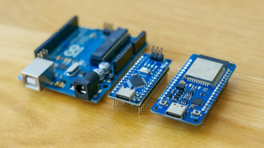
From left to right: Arduino Uno, Arduino Nano & ESP32.
The radio module
The ESP32 comes with built-in WiFi and Bluetooth, but it lacks LoRa support. So, we’ll need a separate chip to handle LoRa. I chose the XL1278-SMT, which is based on Semtech’s sx1278. This module runs on 3.3v for both power and logic levels, just like the ESP32 board hopefully. That’s different from Arduino boards, which operate at 5v.
This tiny evil thing has 1.27mm pin headers that I had to bridge to 2.54mm pin headers for my breadboard.
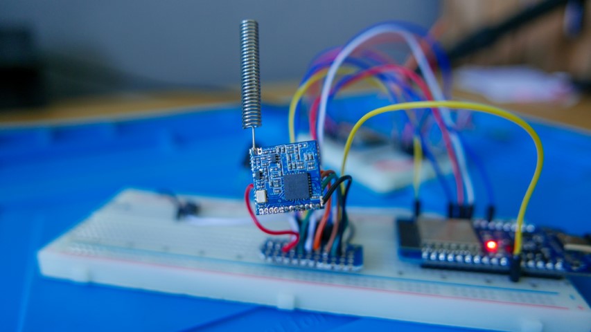
Protoyping the radio communication
For this prototype, I’ve set up a button that toggles the ESP32’s built-in blue LEDs when pressed. The transmitter board on the left uses direct electrical wiring to control the LED, while the receiver board on the right gets the button status via LoRa and acts accordingly.
This is amusing, as there’s no security in place right now. Who knows, someone might think I’m sending out Morse code messages!
Schematic
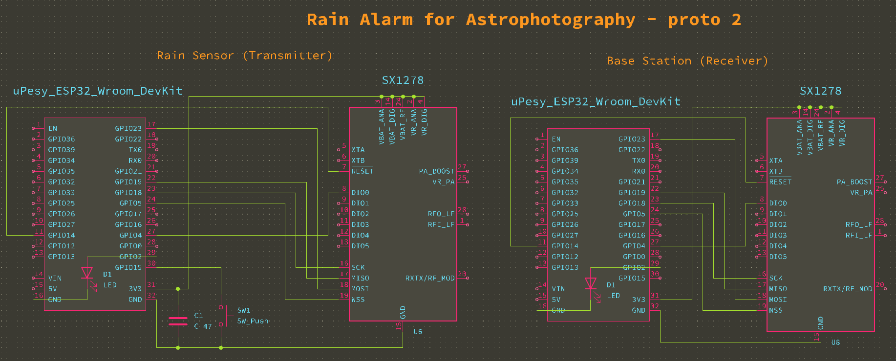
- Both the ESP32 and the XL1278-SMT LoRa module connect in the same way on both circuits, using the
SPI bus. The uPesy board features a tiny blue LED,D1, connected to the GPIO2 output. - I’m using a switch, labeled
SW1, to simulate a rain trigger. The switch is connected to the ESP32 board viaGPIO15, configured asINPUT_PULLUP. The board comes with a built-in pull-up resistor, so there’s no need for an external one 💝. - When you press the switch
SW1, it changes the state of the rain sensor’s LED, labeledD1. The base station’s LED follows the switch state as well thanks to the wireless com. - Lastly, I needed a capacitor
C1to stabilise the boot of the XL1278-SMT module on the transmitter side, due to some voltage fluctuation issues.
Take away
We’ve learn a few things:
- The ESP32 is looking pretty solid, it’s safe to assume this will be the board I will use for the final product.
- LoRa rocks too in terms of range and reliability. I was able to reach 200 meters of coverage with a 100% stable transmission between my house and outside on the street, with countless walls in between. That’s very good considering having not fine tuned anything and the poor PCB antenna, and I don’t even need more than that.
Next step
Next on the agenda: speakers for the base station.
There’s a bunch of tweaks to make on this prototype, like:
- Switching the ESP32 to deep sleep to kill the Bluetooth and WiFi, dropping from 200mA to 20mA (easy).
- Leveraging ESP32 timers so we don’t have to poll the switch or blast LoRa packets at CPU clock speed (medium-level stuff).
- Getting the LoRa module into sleep mode and wake up when needed (tricky).
- Secure the LoRa communication (medium-level stuff).
- Buy the proper version of the LoRa to comply with EU regulation.