27 August 2023 astrophotography DIY electronics
Rain Alarm for Astrophotography proto 1 - Rain Sensor
So, asking around and searching online, there is no evidence of a ready-to-buy rain alarm that would fit for astrophotography.
I’m going to build one.
Need context
Deep-sky astrophotography involves capturing images of deep-sky objects (DSOs) such as galaxies, nebulae, and star clusters.
You’ll need to accumulate hours of exposure time and process the data to reveal this faint and ancient light from deep space.
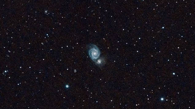
Messier 51, or the Whirlpool Galaxy, with 60 x 60 seconds of lights data on a small refracting telescope 72ED.
Astrophotography is all about hauling your pricey gear into your yard, maybe on a random Tuesday night because the sky and moon are playing nice, even though you’re clocking in the next morning. You spend an hour getting everything up and running, and there nothing to do anymore as it runs on its own: at this point, you just want to go back inside and sleep.
But what happens if the forecast is poor and it rains overnight?
I interviewed several astrophotographers, and they either said they rely on hope or joked about taking sleep aids to sleep.
Personally, I relied on some rain alert mobile apps, but a week of evaluation showed they can still produce false positives and negatives. Additionally, the app may be draining my phone’s battery so the phone kills it first.
I’ll take my chance with a DIY rain alarm.
Scoping the project
As a dad, the struggle isn’t foreign to me at all—it’s pretty much identical to having a snoozing infant. You’re torn between catching some sleep and making sure your baby is okay.
👉 And you invest in a baby monitor.
That’s exactly what I want to do: create a baby monitor for astrophotography.
Early specs
We’re going to build a device with the same characteristics that led me to choose my baby monitor:
- Plug and play and self-sufficient: no need to connect to a computer or mobile phone.
- No third dependencies: No mobile app, no Cloud (the device will not be dead because of f-word software obsolescence).
- Fair wireless range: No WiFi, No Bluetooh.
- Minimal to no configuration.
- Outstanding reliability.
There will be a rain sensor and the base station, both communicating via radio. If it rains, the base station will sound an alarm. That’s it.
Protoyping the rain sensor
For that, I’m using an Arduino Uno that I already have, along with a rain sensor module that I’ve purchased specifically for this project.
And here we go with the first prototype:
Schematic
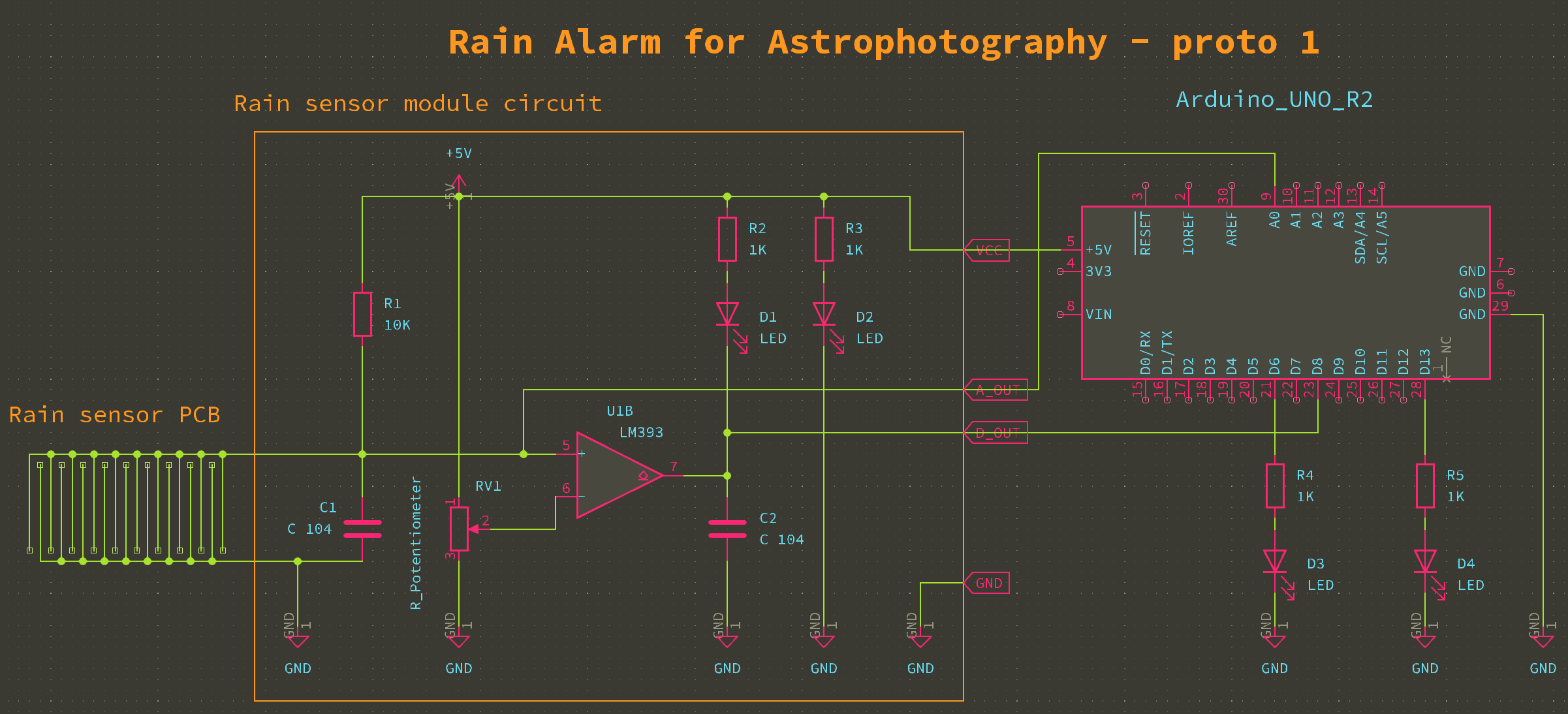
- The rain sensor PCB (roundish PCB in the video) in connected to the rain sensor module circuit. The more water on the PCB, the more you reduce its electrical resistance.
- The rain sensor module circuit uses an Op-Amp (Operational Amplifier) Circuit LM393 to convert the analog output of the rain sensor PCB to a digital output.
Water on the rain sensor PCB will increase the voltage on the Op-Amp
Input 5on this design, andOutput 7will return 0v or 5v depending on the threshold set by the potentiometerRV1. The circuit also provides the original analog output, which allows you to sidestep the digital conversion process entirely. I purchased this along with the rain sensor PCB, but I’m not sure it’s worth using it. That’s what the prototype is for. - The Arduino Uno and surrounding circuitry interfaces with both the digital and analog outputs from the rain sensor module circuit.
The digital signal from the sensor links up with the
D8pin on the Arduino Uno. This pin reads the signal as either HIGH or LOW, triggering theD4LED to switch ON or OFF accordingly. The analog signal feeds into theA0pin on the Arduino Uno. This pin interprets the analog signal as a numerical value ranging from 0 to 1023. TheD3LED has voltage applied to it based on the numerical value, which influences the brightness of the LED.
Take away
We’ve learn a few things:
- It’s fun.
- Blogging about the prototype triples the amount of work required.
- The core feature is working: the rain sensor PCB is able to detect rain in a reliable way.
- The analog output experiences slight fluctuations, especially when the PCB is wet. However, this is not a concern for our use case, as our primary goal is to detect raindrops.
- The Op-Amp circuit and its digital output appear to be unnecessary, which is good news. This eliminates both the cost and the uncertainty associated with the resistive potentiometer settings. We can simply rebuild the Ohm’s law design with the 10k resistor (
R1in the schematic) and handle the threshold via software. We might also need to reintroduce a capacitor (C 104in the schematic) to the rain sensor PCB pins. My suspicion is that it may only be essential for the LM393 Op-Amp circuit.
I’m all for more software and less hardware 🙃.
Next step
We’ll prototype the radio communication between the rain sensor and the base station.