Creating a DIY remote for ASCOM astronomy hardware
You are reading a blog post about the making of poto-wanderercover. You can find the source code on GitHub.
Where it all started
I recently bought a second-hand motorized flat field panel to help with my astrophotography, a WandererCover from WandererAstro.
Like most of the astronomy hardware out there, this device is managed via the standard ASCOM protocol. The usual setup is a Windows computer with the N.I.N.A. software suite.
Another popular setup for astrophotography is to use the ZWO ASIAIR, which is small, plug-and-play and driven from a phone app, but… vendor-locked. I can’t plug that hardware into it. I’ll try anyway ¯\(ツ)/¯.
How to train your WandererCover
Luckily, the company provides concise, clear documentation. It shows the serial communication behind the ASCOM abstraction: UART, more precisely.
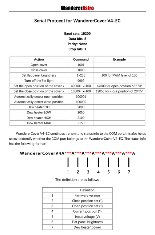
Let’s run a quick test to check. For that, I’m using a Windows computer, connecting the USB cable and opening a serial connection with PuTTY.
Quite low-tech, but it works: the device sends its status.
Typing 255 in the terminal turns the light to maximum brightness, and the new status confirms it too.
Scoping my project
I’ll need to build some electronics to control the panel. I should be able to map the panel’s commands I need onto three ON-OFF-ON switches, aka three-position switches:
| switch | commands | description |
|---|---|---|
| lid | 1001 / 1000 | open/close the lid |
| light | 9999 / 10 / 100 | off/low/high brightness |
| heater | 2000 / 2050 / 2100 | off/low/high heater |

ESP32
I’ll need a board. The usual suspects are the Arduino boards, but I want something that I can expand later on. They’re limited for this, or quickly get expensive (shields, etc.). On the other hand, ESP32 chips offer Wi-Fi and Bluetooth out of the box, and I gained some experience with them on my other project, Rain Alarm for Astrophotography.
For the serial communication over USB (the WandererCover only talks over USB), I’ll need a USB-to-TTL converter. The layout of the circuit would be the following:
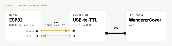
The proof of concept code is the following, using the Arduino framework for ESP32:
#include <HardwareSerial.h>

// Set up UART for the WandererCover V4-EC communication via USB-to-TTL device.
HardwareSerial mySerial(1);

#define RX_PIN (GPIO_NUM_16)
#define TX_PIN (GPIO_NUM_17)

String readStatus();

void setup()
{
    // Serial communication for debugging (nothing related to our serial communication we try to achieve).
    Serial.begin(115200);
    while (!Serial)
        ;

    // Start UART communication.
    mySerial.begin(19200, SERIAL_8N1, RX_PIN, TX_PIN);

    // Log to console that the communication is initialized.
    Serial.println("WandererCover V4-EC communication initialized.");
}

void loop()
{
    // Try to read status info from WandererCover.
    if (mySerial.available())
    {
        String status = readStatus();
        Serial.println(status);
    }
}

String readStatus()
{
    String status = "";
    while (mySerial.available())
    {
        char c = mySerial.read(); // Read each byte received
        status += c;              // Append to status string
    }
    return status;
}
But that’s not working.
Reading back the CH340 sheet (the USB controller of my ESP32 board) and ESP32 Espressif documentation about USB Host, I realize my architecture is probably wrong. Some ESP32 chips (the S2 and S3) can act as a USB host and communicate directly with the WandererCover… But for that, I need to use the usb/usb_host.h library, which probably means giving up on the Arduino framework and using the ESP-IDF framework instead. And now that we’re here, I also notice that my specific ESP32-WROOM-32 board doesn’t support USB host mode 🤦.
Raspberry Pi Zero W
At this point, I give in to laziness: a full Linux environment and a real USB port. I have a Raspberry Pi Zero W lying around and this board has all we need (data USB, GPIO…) while remaining compact.
It’s been a while since I last used a Raspberry Pi, and I’m glad to discover Raspberry Pi Imager, which flashes the SD card in a few minutes.
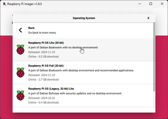
…And 20 long minutes to run apt update && apt upgrade -y. We’re clearly not using the board for its CPU!
From there, it’s easy to test via SSH:
# search the USB port name used.
dmesg | grep tty
# should list ttyUSB0 (some devices show up as ttyACM0).

ls /dev/ttyUSB0 /dev/ttyACM0

# close the lid of the panel.
echo '1000' > /dev/ttyUSB0

# live test of the device with screen.
screen /dev/ttyUSB0 19200
Let’s prepare the environment for scripting with Python:
python --version
# 3.11.2

# isolate the environment to avoid conflicts with the system packages.
sudo apt install python3-venv
python3 -m venv poto-wanderercover
source poto-wanderercover/bin/activate

# install the minimum package to control the serial port.
pip install pyserial
Blinking the light with Python is easy:
import time
import serial

ser = serial.Serial('/dev/ttyUSB0', 19200)
ser.write(b'9999') # Turn off the light
time.sleep(3)
ser.write(b'255') # Turn on the light at maximum brightness
time.sleep(3)
ser.write(b'9999') # Turn off the light
The next step will be to wire the Python script to a physical switch, using the GPIO pins. But the proof of concept already works!
A surprise on the way
WandererAstro released a new firmware version for the WandererCover claiming to be compatible with ASIAIR. They outpaced me on that one!
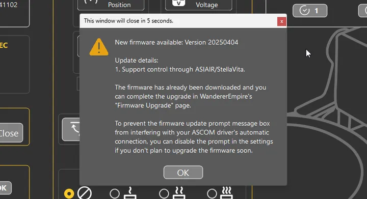
Well, looking at it closer, it’s far from handy: it works by switching the 12V off and on at specific intervals. The documentation is a bit awful, so I asked an LLM for a cheat sheet, but it remains a bit complex to use 🫠:
## WandererCover - Power Control Cheat Sheet
### Standby Mode
- `DC ON for 10+ sec` -> Enter standby mode
### Open/Close Cover
- `OFF -> ON (2-4 sec)` -> Opens or closes cover based on current position
### Cycle Brightness Levels
- `OFF -> ON (<2 sec)` -> Cycles through 9 preset brightness levels
  (Repeat to keep cycling)
### Turn Brightness Off
- `OFF -> ON (4-10 sec)` -> Sets brightness to 0 instantly
### Custom Brightness (via ASIAIR)
1. `OFF -> ON (4-10 sec)` -> Set brightness to 0
2. `OFF -> ON (2-4 sec)` -> Set to Custom Brightness 1
3. `OFF -> ON (2-4 sec)` -> Set to Custom Brightness 2
4. `OFF -> ON (2-4 sec)` -> Set to Custom Brightness 3
- Repeat to cycle through the presets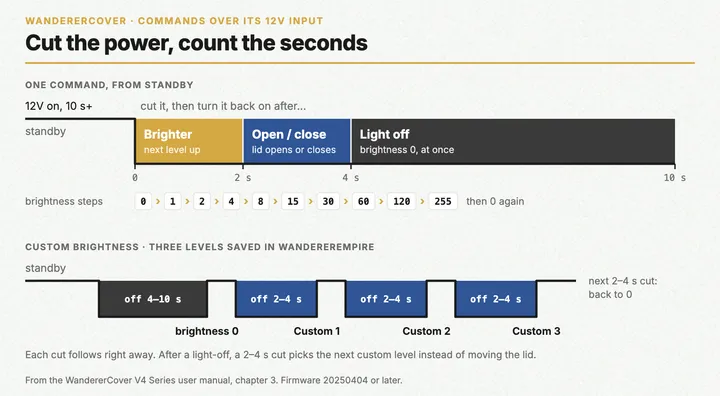
All things considered, it’s smart: the ASIAIR Plus can switch each of its 12V ports on and off.
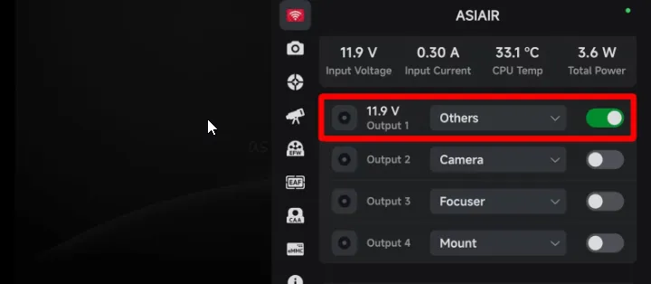
But with my ASIAIR Mini (it can’t switch its ports), I would need to manually unplug the cable or make a custom cable with a switch.
I’m not always pragmatic: I stick to my idea of switches, which are easier to use. I’ll regret the maintenance burden later.
Reading three switches
Each ON-OFF-ON switch takes two GPIO pins. Its middle pin carries 3.3V, and each outer pin goes to a GPIO input with the Pi’s internal pull-down resistor on. With the lever on one side, one pin reads high; on the other side, the other one does; in the center, both stay low.
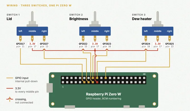
In code, reading a switch looks like this:
import RPi.GPIO as GPIO

GPIO.setmode(GPIO.BCM)
GPIO.setup(pin_a, GPIO.IN, pull_up_down=GPIO.PUD_DOWN)
GPIO.setup(pin_b, GPIO.IN, pull_up_down=GPIO.PUD_DOWN)

a = GPIO.input(pin_a)
b = GPIO.input(pin_b)
if a and not b:
    position = "left"
elif b and not a:
    position = "right"
elif not a and not b:
    position = "center"
else:
    position = "invalid"  # both high, a wiring problem
The panel has a mind of its own
The WandererCover sends its status line on its own, and receiving one means it’s ready for a command:
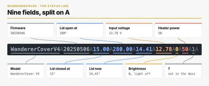
From there, the documentation is silent, and the panel has its own ways:
- It’s stateful. It ignores brightness and heater commands while the lid is moving or open, and opening the lid turns the light off.
- Its signals are unreliable. It sends an undocumented
doneonce the lid stops moving: sometimes very late, sometimes never. The current position in the status line can’t be trusted either. - It takes one command at a time. Send two in a row and the second one can be dropped. So the controller sends at most one command per status line, then waits for the next.
So flipping the light on right after closing the lid did nothing, while the controller, having sent its command, was sure the light was on.
The commit log kept score of my attempts:
- Resend every command regularly, and let the panel sort it out. Wrong.
- Wait until the reported position is within 1° of the closed one, then resend. Not reliable, since the position isn’t.
- A countdown: once the lid moves, wait, then resend the brightness and heater commands. 10 seconds wasn’t enough, 20 is.
- The same countdown, plus a queue: a lid switch flipped while the lid is still moving is applied once the countdown ends.
The least clever approach is the one that works.
# Seconds to wait once the lid moves, before resending the brightness and
# heater commands: the panel ignores them while the lid is moving or open.
TIME_TO_WAIT_AFTER_CLOSE = 20
Worth mentioning: VS Code’s remote development doesn’t run on the Pi Zero W, so I wrote the code on my computer, pushed it with rsync and tested each approach by hand.
Running on its own
It’s meant to be plug and play: power the box and it works, no Wi-Fi, SSH or keyboard involved. So the script starts at boot as a systemd service, and Restart=always brings it back 10 seconds after a crash:
[Service]
WorkingDirectory=/home/pi/poto-wanderercover
ExecStart=/bin/bash -c 'source /home/pi/poto-wanderercover/poto-wanderercover/bin/activate && python main.py'
Restart=always
RestartSec=10

[Install]
WantedBy=multi-user.target
A box for it
Last part, the hardware. The case started as greygoo’s parametric screwable case (CC BY), and I shaped the rest with an LLM. OpenSCAD suits that well: a model is code, a few parameters on top, then shapes added and cut out, so a change can be asked for in words.
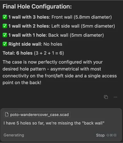
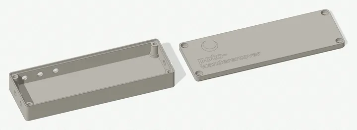
It still took a few prints. The switch holes moved to the other wall, their spacing went from 12 to 15 mm, and the pockets for the bolt heads took three sizes, from 5.7 to 6.8 mm, before I noticed the heads are hexagonal.
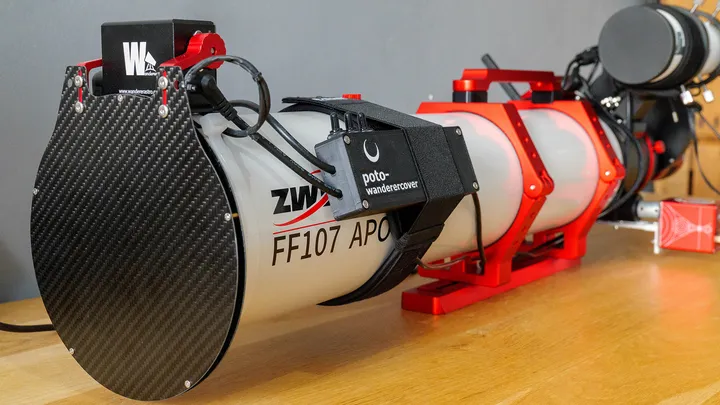
Everything fits in, closed with four M3 bolts, the three switches sticking out of one side. The rig’s 12V comes in at one end and goes back out to the panel at the other, next to the USB cable. On the way, a DC-DC step-down converter set to 5V powers the Pi.
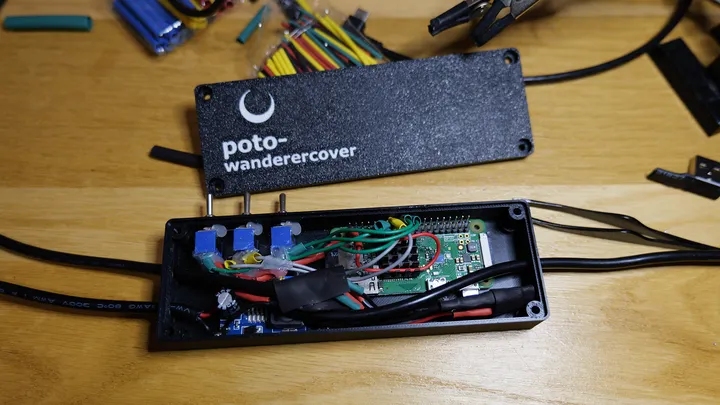
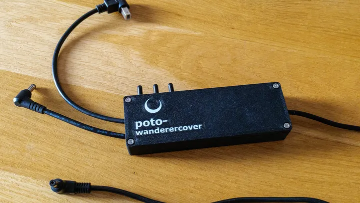
Strapped to the tube, it sits right behind the panel it drives.
Wrapping up
The panel now opens, lights up and heats from three switches on the tube, with no Windows computer and no ASIAIR involved.
Everything is on GitHub: the code, the wiring and the case to print, in poto-wanderercover. I don’t think I’ll build a device this niche again any time soon.